Tractive Effort
“Tractive effort” (TE) is the force applied by a locomotive for moving itself and a train. Tractive effort or tractive force is measured in kilo-Newtons (kN) or pounds force (lbf) where 1 kN = 228.4 lbf.
As with “power”, there are different methods of measuring tractive effort:
- Drawbar tractive effort – the force applied by a locomotive to the connection to its train. If the locomotive is running light (with no train) then its drawbar TE = 0.
- Wheel-rim tractive effort – the force applied by a locomotive to the rails through its driving wheels. The difference between Wheel-rim TE and Drawbar TE is the force required to move the locomotive in overcoming internal (mechanical), rolling and wind resistances.
- Indicated or Cylinder tractive effort – a hypothetical force estimated by adding to the Wheel-rim TE the force required to overcome the frictional resistance of piston against cylinder, piston-rod against gland, crosshead against slidebar and the rotational resistance of big and small-end bearings. In the case of the 5AT (FDC 1.1 lines 46 and 47), the Wheel-rim TE is estimated to be 93% of Cylinder TE at starting and 96% when running.
- Starting tractive effort – the pulling force exerted by a locomotive when starting from rest.
The commonly used formula for calculating a locomotive’s starting Tractive Effort is

The above formula is simplified in that it takes no account of the piston rod diameter which reduces the effective area of (and therefore the force applied to) the rear side of the piston. In the case of the 5AT (and a few other locomotive types) the presence of a tail-rod reduces the effective area of both sides of the piston. [Thanks to Larry Dean for drawing my attention to an error in the formula which is now corrected.]
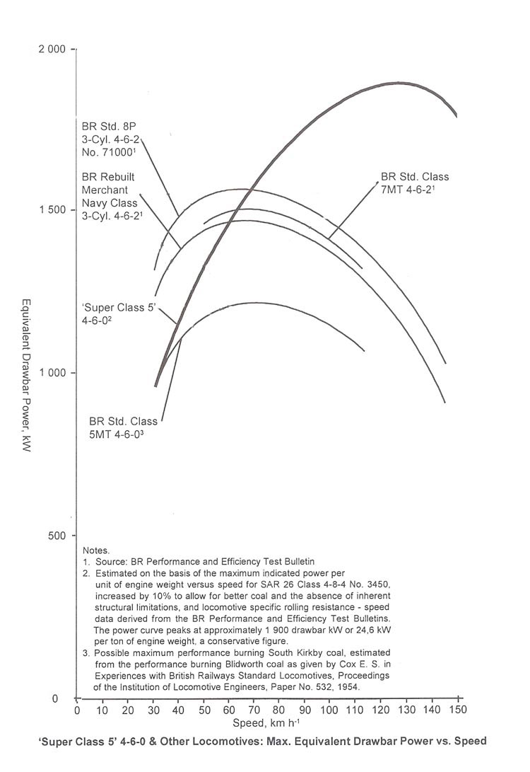
A locomotive’s starting tractive effort only provides an indication of the size of train that it can start. It does not measure the ability of the locomotive to pull a train at speed. This is because tractive effort reduces as speed increases. A locomotive that can maintain a high tractive effort at speed is a more “powerful” locomotive than one that cannot since Power = Tractive Force x Speed.
The relationship between TE and Speed for a variety of locomotives is illustrated in the diagram below (copied from page 499 of Wardale’s book “Red Devil and Other Tales from the Age of Steam“) in which it can be seen that the TE of the “Super Class 5 4-6-0 (5AT) remains higher than even the most powerful British Pacifics once their speed exceeds 70 km/h. The 5AT’s ability to maintain high TE at speed is a measure of its ability to deliver and make use of steam that is supplied to the cylinders i.e. “good breathing”. (The diagram can be compared to the Power – Speed diagram copied from the same page, which is shown on the Drawbar Power page of this section of the website.)

It should be noted that the actual wheel-rim tractive effort of a locomotive varies considerably as the wheels rotate. This variation is most pronounced in two and four-cylinder machines with cranks set 90 degrees apart. When one piston is at mid-stroke where it generates maximum torque, the second piston is at front or back dead centre where it provides zero torque. The maximum starting torque is half what you’d get if both pistons were acting in unison – hence the factor 2 in the bottom line of the equation.
Calculation of tractive force is further complicated by changes in crank angle as the wheels rotate and by the variation in piston force resulting from “cut-off” and the subsequent expansion of the steam in the cylinder. This can be seen in the diagram below showing the variation in tractive force as calculated for the 5AT, at starting, at max drawbar-power output and at maximum speed. It also compares the starting the nominal starting tractive effort when new and when wheels and cylinders are part worn (both of which result in an increase in TE).

A locomotive’s tractive effort (at all speeds) is limited by its adhesive weight and the available coefficient of adhesion between wheel and rail, as illustrated in the above diagram and as discussed in more detail on the Adhesion page of this website.
The maximum speed that a locomotive can attain with any given train occurs when the locomotive’s drawbar tractive effort exactly equals the rolling resistance of the train (see the Rolling Resistance page of this website).
The acceleration that a locomotive can achieve with any given train can be calculated by applying Newton’s Second Law of Motion – i.e. by subtracting the rolling resistance of the locomotive and train from the locomotive’s wheelrim tractive effort, and dividing the difference by the total mass of the locomotive and train.